

4G LTE MEASUREMENT HANDOVER
HANDOVER INTRA MME/SGW
 |
HANDOVER INTRA MME/SGW |
Evolution of 4G LTE networks ( Read Full Article )
4G HANDOVER INTRA E-UTRAN
Intra E-UTRAN Handover is used to hand over a UE from a source eNodeB to a target eNodeB using X2 when the MME is unchanged.The intra E-UTRAN HO in RRC_CONNECTED state is UE assisted NW controlled HO, with HO preparation signalling in E-UTRAN.
To
prepare the HO, the source eNB passes all necessary information to the target
eNB (e.g. E-RAB attributes and RRC context) and UE accesses the target cell via
RACH following a contention-free procedure using a dedicated RACH preamble.
The
HO procedure is performed without EPC involvement, i.e. preparation messages
are directly exchanged between the eNBs.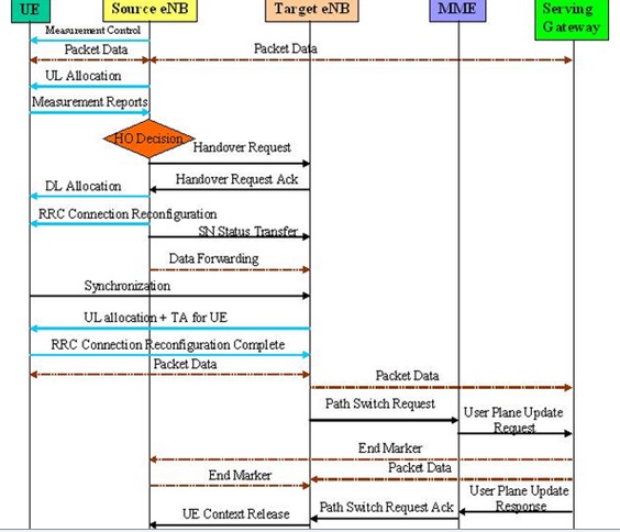 |
HANDOVER INTRA E-UTRAN |
DID YOU KNOW:-
Detailed
explanation of above scenario is below.
•
The source eNB configures the UE measurement procedures according to the area
restriction information. UE sends MEASUREMENT REPORT by the rules set by i.e.
system information, specification etc.
•
Source eNB makes decision based on MEASUREMENT REPORT and RRM information to
hand off UE and issues a HANDOVER REQUEST message to the target eNB passing
necessary information to prepare the HO at the target side.
•
Admission Control may be performed by the target eNB dependent on the received
E-RAB QoS information to increase the likelihood of a successful HO. The target
eNB configures the required resources according to the received E-RAB QoS
information.
•
Target eNB prepares HO with L1/L2 and sends the HANDOVER REQUEST ACKNOWLEDGE to
the source eNB. The HANDOVER REQUEST ACKNOWLEDGE message includes a transparent
container to be sent to the UE as an RRC message to perform the handover.
•
The UE receives the RRCConnectionReconfiguration message with necessary
parameters (i.e. new C-RNTI, target eNB security algorithm identifiers, and
optionally dedicated RACH preamble, target eNB SIBs, etc.) and is commanded by
the source eNB to perform the HO.
•
The source eNB sends the SN STATUS TRANSFER message to the target eNB to convey
the uplink PDCP SN receiver status and the downlink PDCP SN transmitter status
of E-RABs for which PDCP status preservation applies (i.e. for RLC AM).
•
After receiving the RRCConnectionReconfiguration message including the
mobilityControlInformation , UE performs synchronisation to target eNB and
accesses the target cell via RACH.
•
The target eNB responds with UL allocation and timing advance.
•
UE sends the RRCConnectionReconfigurationComplete message (C-RNTI) to confirm
the handover to the target eNB to indicate that the handover procedure is
completed for the UE. The target eNB verifies the C-RNTI sent in the
RRCConnectionReconfigurationComplete message. The target eNB can now begin
sending data to the UE.
•
The target eNB sends a PATH SWITCH message to MME to inform that the UE has
changed cell.
•
The MME sends an UPDATE USER PLANE REQUEST message to the Serving Gateway.
•
The Serving Gateway switches the downlink data path to the target side. The
Serving gateway sends one or more "end marker" packets on the old
path to the source eNB and then can release any U-plane/TNL resources towards
the source eNB.
•
Serving Gateway sends an UPDATE USER PLANE RESPONSE message to MME.
•
The MME confirms the PATH SWITCH message with the PATH SWITCH ACKNOWLEDGE
message.
•
By sending UE CONTEXT RELEASE, the target eNB informs success of HO to source
eNB and triggers the release of resources by the source eNB. The target eNB
sends this message after the PATH SWITCH ACKNOWLEDGE message is received from
the MME.
•
Upon reception of the UE CONTEXT RELEASE message, the source eNB can release
radio and C-plane related resources associated to the UE context. Any ongoing
data forwarding may continue.
 |
HANDOVER INTRA E-UTRAN (X2) |

 |
HANDOVER INTRA E-UTRAN (X2) |

 |
HANDOVER INTRA E-UTRAN (X2) |
TIPS:-
ANR HO
LTE UE can detect intra LTE neighbours without
neighbour lists which simplifies network management.
The UE reports other cell IDs to the eNodeB. If the
target cell ID is known by eNodeB, it will proceed with the handover.
If the target is not known by eNodeB and no is X2
enabled, the eNodeB asks UE to decode global cell id of the target cell.
The eNodeB finds out the target cell’s IP address
from O&M, enables an X2 connection to the target cell and proceeds with the
handover
HANDOVER INTRA MME/SGW (S1)
 |
PREPARATION PHASE |
 |
EXECUTION PHASE |
 |
COMPLETION PHASE |
HANDOVER INTRA MME/SGW (S1)
Step
1. The
source eNodeB decides to initiate an S1-based handover to the target eNodeB.
This can be triggered e.g. by no X2 connectivity to the target eNodeB, or by an
error indication from the target eNodeB after an unsuccessful X2-based
handover, or by dynamic information learnt by the source eNodeB.
Step 2. The
source eNodeB sends Handover Required (Direct Forwarding Path Availability,
Source to Target transparent container, target eNodeB Identity, CSG ID, CSG
access mode, target TAI, S1AP Cause) to the source MME. The source eNodeB
indicates which bearers are subject to data forwarding. Direct Forwarding Path
Availability indicates whether direct forwarding is available from the source
eNodeB to the target eNodeB. This indication from source eNodeB can be based on
e.g. the presence of X2. The target TAI is sent to MME to facilitate the
selection of a suitable target MME. When the target cell is a CSG cell or a
hybrid cell, the source eNodeB shall include the CSG ID of the target cell. If
the target cell is a hybrid cell, the CSG access mode shall be indicated.
Step 3. The source MME selects the target MME and if it has determined to relocate the MME, it sends a Forward Relocation Request (MME UE context, Source to Target transparent container, RAN Cause, target eNodeB Identity, CSG ID, CSG Membership Indication, target TAI, MS Info Change Reporting Action (if available), CSG Information Reporting Action (if available), UE Time Zone, Direct Forwarding Flag) message to the target MME. The target TAI is sent to the target MME to help it to determine whether S GW relocation is needed (and, if needed, aid SGW selection).
The source MME shall perform access control by checking the UE's CSG subscription when CSG ID is provided by the source eNodeB. If there is no subscription data for this CSG ID or the CSG subscription is expired, and the target cell is a CSG cell, the source MME shall reject the handover with an appropriate cause.
The MME UE context includes IMSI, ME Identity, UE security context, UE Network Capability, AMBR, Selected CN operator ID, APN restriction, Serving GW address and TEID for control signalling, and EPS Bearer context(s).
An EPS Bearer context includes the PDN GW addresses and TEIDs (for GTP-based S5/S8) or GRE keys (for PMIP-based S5/S8) at the PDN GW(s) for uplink traffic, APN, Serving GW addresses and TEIDs for uplink traffic, and TI.
RAN Cause indicates the S1AP Cause as received from source eNodeB.
The source MME includes the CSG ID in the Forward Relocation Request when the target cell is a CSG or hybrid cell. When the target cell is a hybrid cell, the CSG Membership Indication indicating whether the UE is a CSG member shall be included in the Forward Relocation Request message.
The Direct Forwarding Flag indicates if direct forwarding is applied, or if indirect forwarding is going to be set up by the source side.
The target MME shall determine the Maximum APN restriction based on the APN Restriction of each bearer context in the Forward Relocation Request, and shall subsequently store the new Maximum APN restriction value.
If the UE receives only emergency services and the UE is UICCless, IMSI can not be included in the MME UE context in Forward Relocation Request message. For emergency attached UEs, if the IMSI cannot be authenticated, then the IMSI shall be marked as unauthenticated. Also, in this case, security parameters are included only if available.
Step 4. If the MME has been relocated, the target MME verifies whether the source Serving GW can continue to serve the UE. If not, it selects a new Serving GW. If the MME has not been relocated, the source MME decides on this Serving GW re-selection.
If the source Serving GW continues to serve the UE, no message is sent in this step. In this case, the target Serving GW is identical to the source Serving GW.
If a new Serving GW is selected, the target MME sends a Create Session Request (bearer context(s) with PDN GW addresses and TEIDs (for GTP-based S5/S8) or GRE keys (for PMIP-based S5/S8) at the PDN GW(s) for uplink traffic, Serving Network, UE Time Zone) message per PDN connection to the target Serving GW. The target Serving GW allocates the S GW addresses and TEIDs for the uplink traffic on S1_U reference point (one TEID per bearer). The target Serving GW sends a Create Session Response (Serving GW addresses and uplink TEID(s) for user plane) message back to the target MME.
Step 5. The
Target MME sends Handover Request (EPS Bearers to Setup, AMBR, S1AP Cause,
Source to Target transparent container, CSG ID, CSG Membership Indication,
Handover Restriction List) message to the target eNodeB. This message creates
the UE context in the target eNodeB, including information about the bearers,
and the security context. For each EPS Bearer, the Bearers to Setup includes
Serving GW address and uplink TEID for user plane, and EPS Bearer QoS. If the
direct forwarding flag indicates unavailability of direct forwarding and the
target MME knows that there is no indirect data forwarding connectivity between
source and target, the Bearers to Setup shall include "Data forwarding not
possible" indication for each EPS bearer. Handover Restriction List is
sent if available in the Target MME.
S1AP Cause indicates the RAN Cause as received from source MME.
The Target MME shall include the CSG ID and CSG Membership Indication when provided by the source MME in the Forward Relocation Request message.
The target eNodeB sends a Handover Request Acknowledge (EPS Bearer Setup list, EPS Bearers failed to setup list Target to Source transparent container) message to the target MME. The EPS Bearer Setup list includes a list of addresses and TEIDs allocated at the target eNodeB for downlink traffic on S1 U reference point (one TEID per bearer) and addresses and TEIDs for receiving forwarded data if necessary. If the UE AMBR is changed, e.g. all the EPS bearers which are associated to the same APN are rejected in the target eNodeB, the MME shall recalculate the new UE-AMBR and signal the modified UE AMBR value to the target eNodeB.
If none of the default EPS bearers have been accepted by the target eNodeB, the target MME shall reject the handover.
If the target cell is a CSG cell, the target eNodeB shall verify the CSG ID provided by the target MME, and reject the handover with an appropriate cause if it does not match the CSG ID for the target cell. If the target eNodeB is in hybrid mode, it may use the CSG Membership Indication to perform differentiated treatment for CSG and non-CSG members.
Step 6. If
indirect forwarding applies and the Serving GW is relocated, the target MME
sets up forwarding parameters by sending Create Indirect Data Forwarding Tunnel
Request (target eNodeB addresses and TEIDs for forwarding) to the Serving GW.
The Serving GW sends a Create Indirect Data Forwarding Tunnel Response (target
Serving GW addresses and TEIDs for forwarding) to the target MME. If the
Serving GW is not relocated, indirect forwarding may be set up in step
8 below.
Indirect forwarding may be performed via a Serving GW which is different from the Serving GW used as the anchor point for the UE.
Indirect forwarding may be performed via a Serving GW which is different from the Serving GW used as the anchor point for the UE.
Step 7. If the MME has been relocated, the target MME sends a Forward Relocation Response (Cause, Target to Source transparent container, Serving GW change indication, EPS Bearer Setup List, Addresses and TEIDs) message to the source MME. For indirect forwarding, this message includes Serving GW Address and TEIDs for indirect forwarding (source or target). Serving GW change indication indicates a new Serving GW has been selected.
Step 8. If
indirect forwarding applies, the source MME sends Create Indirect Data
Forwarding Tunnel Request (addresses and TEIDs for forwarding) to the Serving
GW. If the Serving GW is relocated it includes the tunnel identifier to the
target serving GW.
The Serving GW responds with a Create Indirect Data Forwarding Tunnel Response (Serving GW addresses and TEIDs for forwarding) message to the source MME.
Indirect forwarding may be performed via a Serving GW which is different from the Serving GW used as the anchor point for the UE.
The Serving GW responds with a Create Indirect Data Forwarding Tunnel Response (Serving GW addresses and TEIDs for forwarding) message to the source MME.
Indirect forwarding may be performed via a Serving GW which is different from the Serving GW used as the anchor point for the UE.
Step 9. The
source MME sends a Handover Command (Target to Source transparent container,
Bearers subject to forwarding, Bearers to Release) message to the source
eNodeB. The Bearers subject to forwarding includes list of addresses and TEIDs
allocated for forwarding. The Bearers to Release includes the list of bearers
to be released.
Step 9a. The Handover Command is constructed using the Target to Source transparent container and is sent to the UE. Upon reception of this message the UE will remove any EPS bearers for which it did not receive the corresponding EPS radio bearers in the target cell.
Step 10. The source eNodeB sends the eNodeB Status Transfer message to the target eNodeB via the MME(s) to convey the PDCP and HFN status of the E-RABs for which PDCP status preservation applies. The source eNodeB may omit sending this message if none of the E-RABs of the UE shall be treated with PDCP status preservation.
If there is an MME relocation the source MME sends this information to the target MME via the Forward Access Context Notification message which the target MME acknowledges. The source MME or, if the MME is relocated, the target MME, sends the information to the target eNodeB via the eNodeB Status Transfer message.
Step 11. The source eNodeB should start forwarding of downlink data from the source eNodeB towards the target eNodeB for bearers subject to data forwarding. This may be either direct (step 11a) or indirect forwarding (step 11b).
Step 12. After the UE has successfully synchronized to the target cell, it sends a Handover Confirm message to the target eNodeB. Downlink packets forwarded from the source eNodeB can be sent to the UE. Also, uplink packets can be sent from the UE, which are forwarded to the target Serving GW and on to the PDN GW.
Step 13. The target eNodeB sends a Handover Notify (TAI+ECGI) message to the target MME.
Step 14. If the MME has been relocated, the target MME sends a Forward Relocation Complete Notification () message to the source MME. The source MME in response sends a Forward Relocation Complete Acknowledge () message to the target MME. Regardless if MME has been relocated or not, a timer in source MME is started to supervise when resources in Source eNodeB and if the Serving GW is relocated, also resources in Source Serving GW shall be released.
Upon receipt of the Forward Relocation Complete Acknowledge message the target MME starts a timer if the target MME allocated S GW resources for indirect forwarding.
Step 15. The MME sends a Modify Bearer Request (eNodeB address and TEID allocated at the target eNodeB for downlink traffic on S1 U for the accepted EPS bearers, ISR Activated) message to the target Serving GW for each PDN connection, including the PDN connections that need to be released. If the PDN GW requested UE's location and/or User CSG information (determined from the UE context), the MME also includes the User Location Information IE and/or User CSG Information IE in this message. If the UE Time Zone has changed, the MME includes the UE Time Zone IE in this message. For the case that neither MME nor S-GW changed, if ISR was activated before this procedure MME should maintain ISR. The UE is informed about the ISR status in the Tracking Area Update procedure.
The MME releases the non-accepted dedicated bearers by triggering the bearer release procedure. If the Serving GW receives a DL packet for a non-accepted bearer, the Serving GW drops the DL packet and does not send a Downlink Data Notification to the MME.
If the default bearer of a PDN connection has not been accepted by the target eNodeB and there are other PDN connections active, the MME shall handle it in the same way as if all bearers of a PDN connection have not been accepted. The MME releases these PDN connections by triggering the MME requested PDN disconnection procedure.
When the Modify Bearer Request does not indicate ISR Activated the Serving GW deletes any ISR resources by sending a Delete Bearer Request to the other CN node that has bearer resources on the Serving GW reserved.
Step 16. If the Serving GW is relocated, the target Serving GW assigns addresses and TEIDs (one per bearer) for downlink traffic from the PDN GW. It sends a Modify Bearer Request (Serving GW addresses for user plane and TEID(s), Serving Network) message per PDN connection to the PDN GW(s). The S GW also includes User Location Information IE and/or UE Time Zone IE and/or User CSG Information IE if they are present in step 15. The Serving GW allocates DL TEIDs on S5/S8 even for non-accepted bearers. The PDN GW updates its context field and returns a Modify Bearer Response (Charging Id, MSISDN) message to the target Serving GW. The MSISDN is included if the PDN GW has it stored in its UE context. The PDN GW starts sending downlink packets to the target GW using the newly received address and TEIDs. These downlink packets will use the new downlink path via the target Serving GW to the target eNodeB.
If
the Serving GW is not relocated, but has received the User Location Information
IE and/or UE Time Zone IE and/or User CSG Information IE from the MME in step
15, the Serving GW shall inform the PDN GW(s) about these information that
e.g. can be used for charging, by sending the message Modify Bearer Request
(User Location Information IE, UE Time Zone IE, User CSG Information IE) to the
PDN GW(s) concerned. A Modify Bearer Response message is sent back to the
Serving GW.
If the Serving GW is not relocated and it has not received User Location Information IE nor UE Time Zone IE nor User CSG Information IE from the MME in step 15, no message is sent in this step and downlink packets from the Serving GW are immediately sent on to the target eNodeB.
If the Serving GW is not relocated and it has not received User Location Information IE nor UE Time Zone IE nor User CSG Information IE from the MME in step 15, no message is sent in this step and downlink packets from the Serving GW are immediately sent on to the target eNodeB.
Step 17. The target Serving GW sends a Modify Bearer Response message to the target MME. The message is a response to a message sent at step 15.
If the Serving GW does not change, the Serving GW shall send one or more "end marker" packets on the old path immediately after switching the path in order to assist the reordering function in the target eNodeB.
Step 18. The UE initiates a Tracking Area Update procedure when one of the conditions listed in clause "Triggers for tracking area update" applies.
The target MME knows that it is a Handover procedure that has been performed for this UE as it received the bearer context(s) by handover messages and therefore the target MME performs only a subset of the TA update procedure, specifically it excludes the context transfer procedures between source MME and target MME.
Step 19. When the timer started in step 14 expires the source MME sends a UE Context Release Command () message to the source eNodeB. The source eNodeB releases its resources related to the UE and responds with a UE Context Release Complete () message. When the timer started in step 14 expires and if the source MME received the Serving GW change indication in the Forward Relocation Response message, it deletes the EPS bearer resources by sending Delete Session Request (Cause, LBI) messages to the Source Serving GW. Cause indicates to the Source Serving GW that the Serving GW changes and the Source Serving GW shall not initiate a delete procedure towards the PDN GW. The Source Serving GW acknowledges with Delete Session Response () messages. If ISR has been activated before this procedure, the cause also indicates to the Source S GW that the Source S GW shall delete the bearer resources on the other old CN node by sending Delete Bearer Request message(s) to that CN node.
Step 20. If indirect forwarding was used then the expiry of the timer at source MME started at step 14triggers the source MME to send a Delete Indirect Data Forwarding Tunnel Request message to the S GW to release the temporary resources used for indirect forwarding that were allocated at step 8.
Step 21. If
indirect forwarding was used and the Serving GW is relocated, then the expiry
of the timer at target MME started at step 14 triggers the
target MME to send a Delete Indirect Data Forwarding Tunnel Request message to
the target S GW to release temporary resources used for indirect forwarding
that were allocated at step 6.
 |
HANDOVER IRAT TO 2G/3G |
 |
HANDOVER IRAT TO CDMA2000 1XRTT and HRPD (High Rate Packet Data) |
4G LTE HANDOVER EVENTS

 |
HANDOVER EVENTS A1 |
 |
| HANDOVER EVENTS A2 |
 |
| HANDOVER EVENTS A3 |
 |
HANDOVER EVENTS A4 |
 |
HANDOVER EVENTS A5 |
 |
HANDOVER EVENTS B1 |
 |
HANDOVER EVENTS B2 |
 |
Speed dependent scaling of measurement parameters |
 |
Handover Measurements |
I am extremely impressed along with your writing abilities, Thanks for this great share.
ReplyDelete4G Lte, Handover Measurements Events Performance >>>>> Download Now
Delete>>>>> Download Full
4G Lte, Handover Measurements Events Performance >>>>> Download LINK
>>>>> Download Now
4G Lte, Handover Measurements Events Performance >>>>> Download Full
>>>>> Download LINK Ug
I really appreciate your skilled approach. These square measure items of terribly helpful data which will be of nice use on behalf of me in future.
ReplyDeleteplease how do i get this handover measurements data sets as csv or excel file
ReplyDeleteplease how do i get this handover measurements data sets
ReplyDeleteAt Superfastprocessing, we run a multi-server configuration with high-fault tolerance and load balancers. Our platform is horizontally scalable and always stays highly available for real-time data processing needs.
ReplyDelete
ReplyDeleteGreat Article
Cyber Security Projects
projects for cse
JavaScript Training in Chennai
JavaScript Training in Chennai
I really like it when individuals come together and share thoughts. Great blog, continue the good work!
ReplyDeleteBuy Instagram Followers
really that's great blog i read all off post it's too good
ReplyDeleteBuy Instagram Followers
4G Lte, Handover Measurements Events Performance >>>>> Download Now
ReplyDelete>>>>> Download Full
4G Lte, Handover Measurements Events Performance >>>>> Download LINK
>>>>> Download Now
4G Lte, Handover Measurements Events Performance >>>>> Download Full
>>>>> Download LINK
Thanks for sharing such an nice blog.
ReplyDelete4g Lte
Fanless Industrial Mini PC MNHO-082
Erzurum
ReplyDeleteElazığ
Konya
Zonguldak
Eskişehir
83RUW
Adana
ReplyDeleteElazığ
Kayseri
Şırnak
Antep
UAF
tekirdağ
ReplyDeletetokat
elazığ
adıyaman
çankırı
D62TG5
görüntülüshow
ReplyDeleteücretli show
NK4U
https://titandijital.com.tr/
ReplyDeletemersin parça eşya taşıma
osmaniye parça eşya taşıma
kırklareli parça eşya taşıma
tokat parça eşya taşıma
127Y
antep evden eve nakliyat
ReplyDeletebolu evden eve nakliyat
afyon evden eve nakliyat
tekirdağ evden eve nakliyat
artvin evden eve nakliyat
AAX
ABF92
ReplyDeleteElazığ Evden Eve Nakliyat
Pursaklar Parke Ustası
Aydın Şehir İçi Nakliyat
Van Lojistik
Yenimahalle Fayans Ustası
Trabzon Evden Eve Nakliyat
Urfa Şehir İçi Nakliyat
İzmir Şehir İçi Nakliyat
Bolu Parça Eşya Taşıma
F7EA3
ReplyDeleteOrdu Parça Eşya Taşıma
Kastamonu Şehir İçi Nakliyat
Elazığ Şehir İçi Nakliyat
Çerkezköy Koltuk Kaplama
Bursa Evden Eve Nakliyat
Zonguldak Lojistik
Yenimahalle Parke Ustası
Keep Coin Hangi Borsada
Eskişehir Şehir İçi Nakliyat
3CEC7
ReplyDeleteSilivri Evden Eve Nakliyat
Artvin Evden Eve Nakliyat
buy peptides
Kars Evden Eve Nakliyat
order anapolon oxymetholone
Çerkezköy Evden Eve Nakliyat
https://steroidsbuy.net/steroids/
boldenone
sustanon
A2E55
ReplyDeletebinance referans kodu %20
27DB1
ReplyDeleteardahan mobil sohbet
mobil sesli sohbet
zonguldak sohbet chat
elazığ sohbet sitesi
Bingöl Canlı Sohbet Odası
amasya sesli görüntülü sohbet
Kırklareli Sesli Sohbet Mobil
kilis kadınlarla sohbet
Afyon Kadınlarla Görüntülü Sohbet
F37BE
ReplyDeleteAksaray Mobil Sohbet Bedava
Aksaray Sesli Sohbet Siteleri
yabancı canlı sohbet
Antalya Telefonda Sohbet
Kırşehir Kadınlarla Sohbet
sohbet siteleri
Adıyaman Sesli Sohbet
artvin en iyi ücretsiz sohbet uygulamaları
Hakkari Rastgele Sohbet Siteleri
شركة مكافحة النمل الابيض بالدمام 5WJowEA8pj
ReplyDeleteFD750E5FBD
ReplyDeleteyeni mmorpg
sms onay
türk telekom mobil bozum
güvenilir takipçi satın alma
-